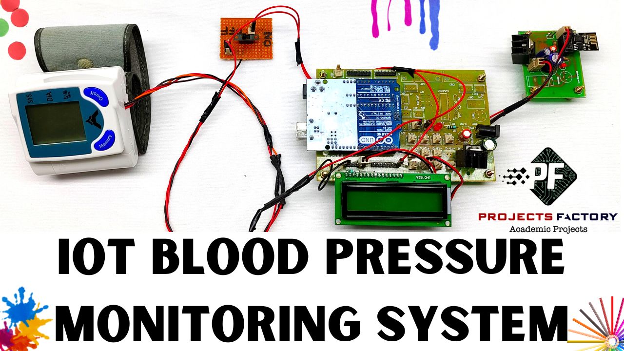
Ambulatory Blood Pressure Monitor 24 Circuit Diagram This article will focus on the dial or pressure gauge type. A typical blood pressure monitor features a neoprene or rubber pump bulb that a medical technician squeezes to build air pressure in the system. Increasing air pressure inflates the constricting band and provides a pressure signal to the manometer or indicating gauge. The video shows a detailed connection for connecting Robosap Blood Pressure Sensor This is a demonstration video on interfacing blood pressure with Arduino. The video shows a detailed
Second, blood pressure monitors are typically battery-powered, so low power consumption is a key design consideration and that favors single-chip solutions. Not surprisingly, therefore, reference designs for blood-pressure monitoring are increasingly built around single-chip solutions that incorporate rich analog functions.
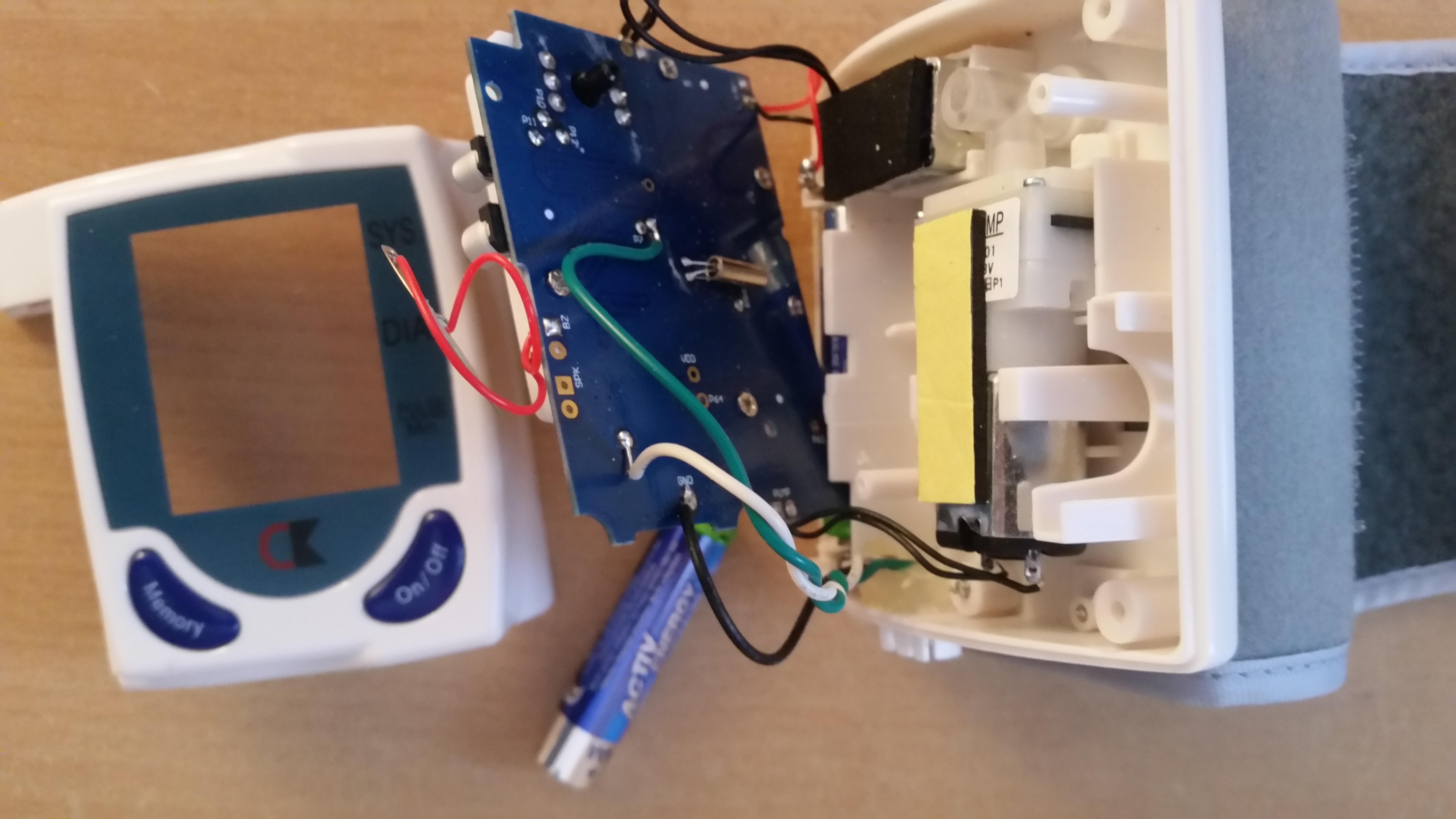
How blood pressure monitor is made Circuit Diagram
3 Blood pressure monitor implementation Blood pressure monitor is implemented using Freescale medical-oriented Kinetis K53 MCUs and Flexis MM devices, which feature the following characteristics: • 16-bit ADC • 12-bit DAC • 2x programmable gain operational amplifiers (OpAmps) • 2x transimpendance amplifiers (TRIAMPS) • Vref generator
A more efficient newer algorithm of detecting systolic and diastolic pressure of human body along with a complete package of an effective user-friendly embedded programmable blood pressure monitoring system has been proposed in this paper to reduce the overall workload of medical personals as well as to monitor patient's condition more conveniently and accurately. Available devices for
PDF Blood Pressure Monitor Circuit Diagram
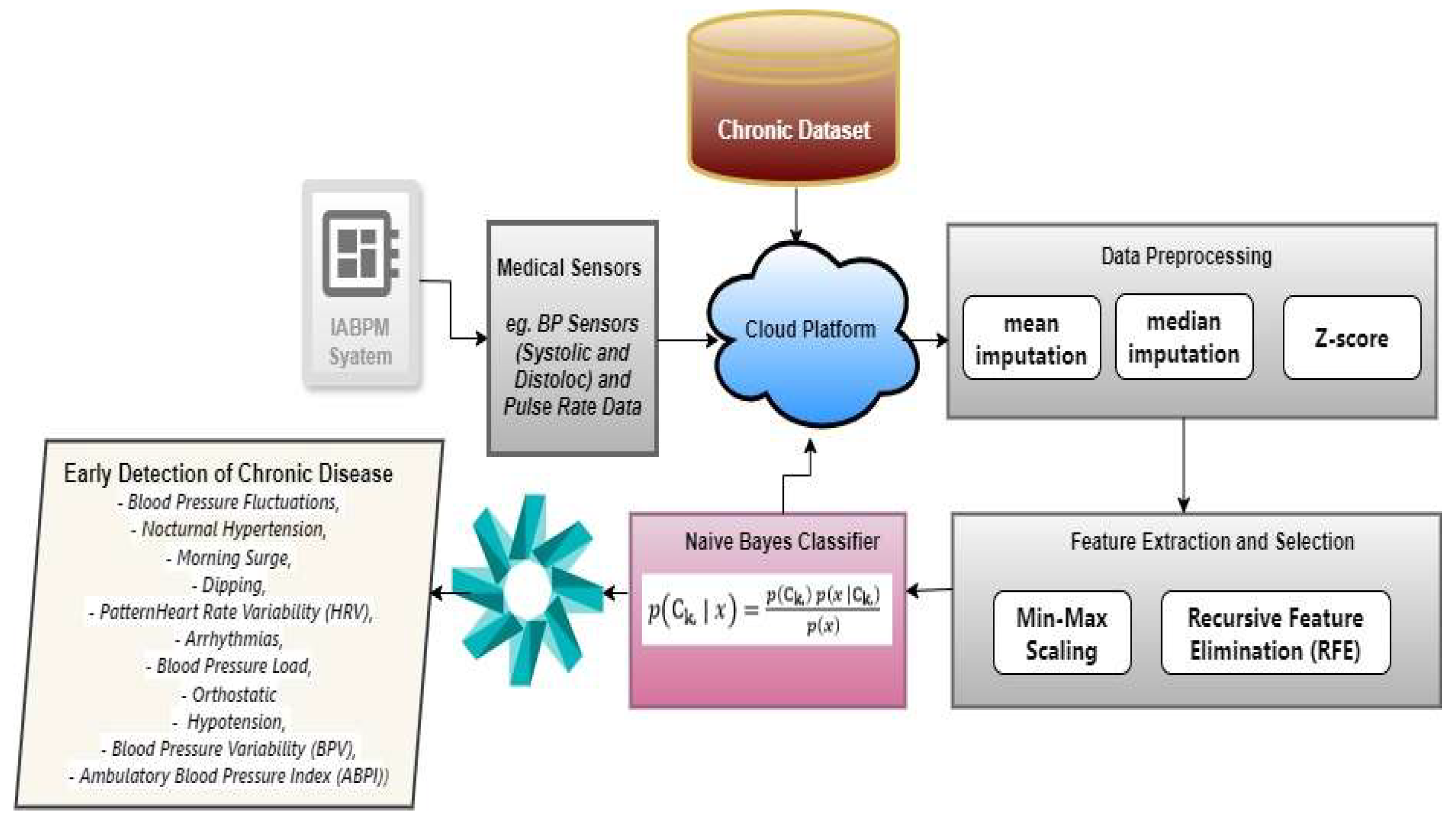
Goal: Continuous Blood Pressure monitoring can provide invaluable information about individuals' health conditions. However, BP is conventionally measured using inconvenient cuff-based instruments

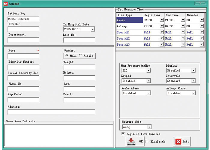
Then upload the code to the Arduino UNO by assembling the circuit shown above. Open the serial monitor and it will automatically connect to Wi-Fi and set up everything. Now click on channels so that you can see the online data streaming, i.e IoT Based Patient Health Monitoring System using ESP8266 & Arduino as shown in the figure here. the air pressure within the cuff that is attached to the manometer by tubing. The manometer head contains mechanical parts that convert the cuff pressure into readings. Arterial BP: The pressure exerted in the arteries in the systemic circulation. Depends on the cardiac output, arterial elasticity, blood viscosity and peripheral vascular
